Panel setup will allow you to create and re-use templates that will automatically place panel fiducials, tooling holes, text labels, coupons, and more. All settings can be saved to a Panel Setup file (*.pan) that may be shared with other colleagues.
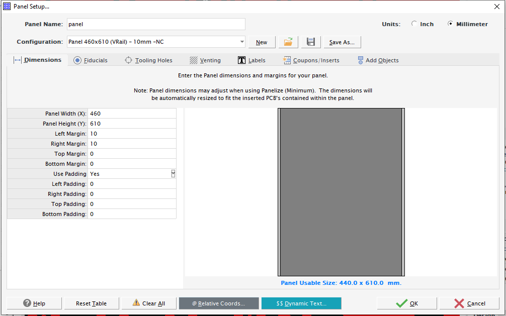
Note: FAB3000 panel templates sizes are "adjustable". So in many cases you only need to create a few templates and they will be automatically resized to fit the array of PCB's contained within the panel.
To access the Panel Setup dialog, go to menu: File / New / Panel...
Note: If the current FAB3000 page displayed is a Panel, you may access Panel Setup directly from the menu: Tools / Panel setup...
- Panel Name: Name of the panel to create. FAB 3000 will create a default name, and you may change.
- Units: Units to use for the entire Panel.
- Configuration: Name of the current FAB 3000 Panel setup file (*.pan). You may use the drop-down to choose any of the available FAB 3000 Panel Setup files available on your computer. FAB 3000 saves all Panel Setup files (*.pan) in its folder <fab3000_home_folder>/panel/
- New: Create a new name for the Panel Setup file.
- Open: Open an existing FAB 3000 Panel setup file (*.pan).
- Save: Save all Panel Setup settings to a FAB 3000 Panel setup file (*.pan) to your local system.
- Save As: Save the FAB 3000 Panel setup file (*.pan) as a different name to your local system.
- Panel Width (X), Height (Y) :
Assign the width and height for the Panel.
Note: FAB 3000 panel templates are "adjustable in size". So in many cases you only need to create a few large templates and they will be automatically shrunk down to fit the array size of PCB's contained within the panel.
- Margin (Left, Right, Top, Bottom):
Available spacing remaining around the perimeter of the panel - which is typically used to place Rails, Fiducials, Tooling holes, Text labels, etc.
- Help:
Press to display specific help for the active Panel Setup feature.
- Clear All:
Clear all Panel setup settings.
- Clear Table:
Only clear the currently displayed table settings - it does not clear the entire Panel Setup settings.
Fiducials |
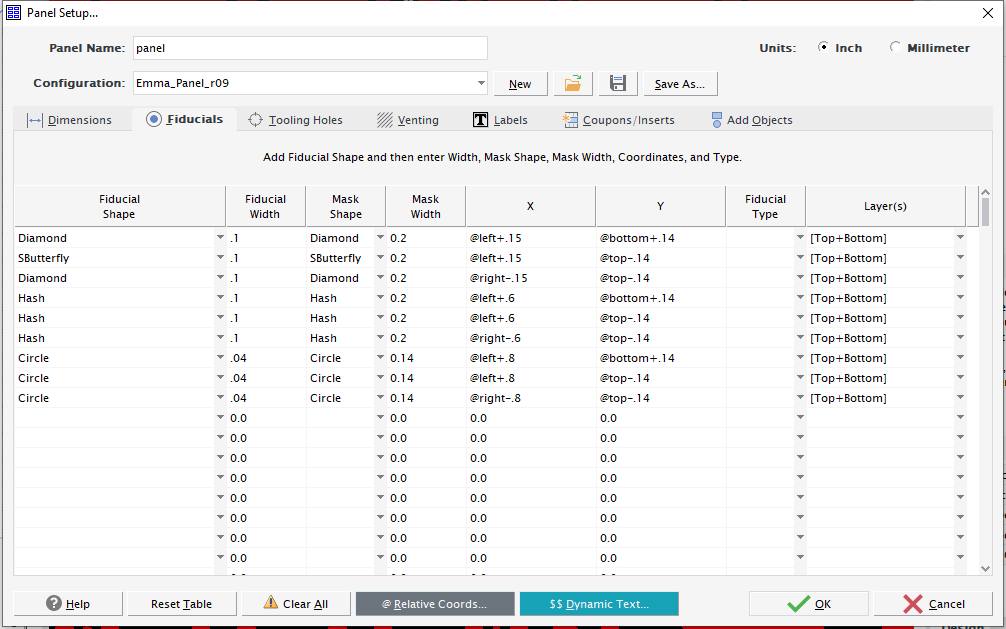
- Fiducial Shape: The width to use for the fiducial. Choose from these available shapes.
- Circle
- Cross
- Diamond
- Hash
- Oblong
- Rectangle
- Target
- Butterfly
- SButterfly
- Fiducial Width: The width to use for the fiducial. Typically this is 1mm.
- Mask Shape: Mask shape are optional. If Mask Shape is empty, or Mask Width is zero - no mask pad will be created, only the fiducial pad. Choose from these available shapes,
- Circle
- Rectangle
- Mask Width: The width to use for the fiducial clearance and mask pad size. Should be larger than the Fiducial Width. Mask width is optional. If Mask Shape is empty, or Mask Width is zero - no mask pad will be created, only the fiducial pad.
- Center Point X, Y: Assign the center point for the fiducial.
- Fiducial Type: Fiducial type is optional. This will attach a Fiducial type attribute to each Fiducial pad created - primary used when exporting ODB++, IPC-2581, and other formats that retain this information.
- Local
- Global
- Panel
- Layer(s): Choose the layers you wish to have the fiducial created on.
IMPORTANT: Relative Panel Coordinates are Recommended:
You may use Relative Panel Coordinates requires the at-sign @ (See below link for examples)
| Tooling Holes |
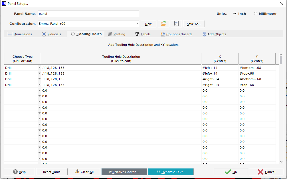
Add NC Tooling Holes and then enter Width, Height, Coordinates, and Rotation.
Available Tooling Hole Shapes:
Drill - A circular hole (not plated)
Slot - A drilled slot .
Width:
The width to use for the tooling hole.
Height (for Slots only):
The height to use for the tooling hole.
Center Point X, Y :
Assign the center point for the tooling hole.
Relative X,Y Coordinates are supported:
You may use Relative X,Y Coordinates requires the at-sign @ (See below for examples)
X = @-1 Y = @0.25 would result in -1 (from Panel Right) and 0.25 (from Panel Bottom)
X = @0.5 Y = @-0.75 would result in 0.5 (from Panel Left) and -0.75 (from Panel Top)
Rotate (for Slots only):
Assign the rotation (in degrees) for the slot. Default is 0.0.
Clearance:
Add a clearance around the tooling hole. Set 0 for no clearance.
| Venting |
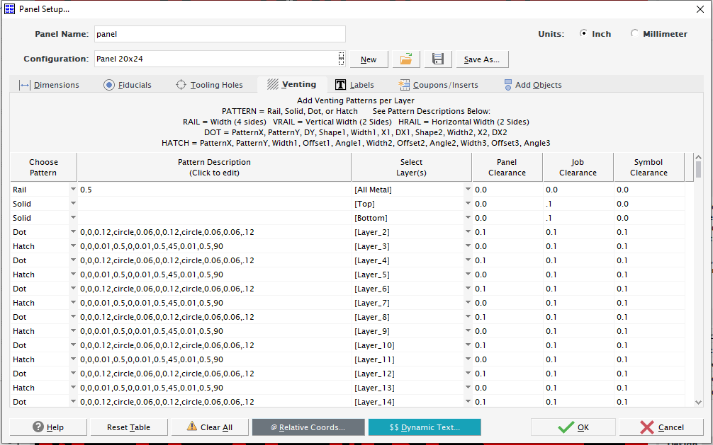
Venting adds copper which isn't connected to any nets on the board and does not affect the functionality. The are various purposes for Venting (i.e Thieving) such as improving etching throughout the entire panel, to improve manufacturing efficiency, and more. Typically small copper circles, squares or even a solid copper plane will be added to larger blank spaces to even out the copper distribution across a copper layer.
- Pattern/ Description : After selecting a Pattern, a default description will be automatically created to assist with configuring the pattern description. Each pattern has different requirements. Typically only Dot and Hatch make use the Pattern descriptions, and must be comma separated.
- Rail Uniform metal places around the perimeter of the panel.
- [width] Overall width of rail (around all 4 sides)
- VRailAdd Vertical Rails only.
- [width] Width of vertical rail (runs along left and right panel sides)
- HRail Add Horizontal Rails only.
- [width] Width of horizontal rail (runs along top and bottom panel sides)
- Solid Add solid copper to available areas/layers.
- No value.
- Dot Add dot patterns to available copper areas/layers.
- [ patternX,patternY,dy,shape1,width1,x1,dx1,shape2,width2,x2,dx2 ]
- Hatch Add hatched patterns to available copper areas/layers.
- [ patternX,patternY,width1,offset1,angle1,width2,offset2,angle2,width3,offset3,angle3 ]
- Rail Uniform metal places around the perimeter of the panel.
- Panel Clearance: Clearance from Panel extents.
- Job Clearance: Clearance from inserted jobs in the panel.
- Symbol Clearance: Clearance from external resources like coupons.
Note: FAB 3000 includes several sample Panel Setup files (*.pan) which make use of various venting patterns. We recommend trying those samples and evaluating the venting pattern results.
| Labels |
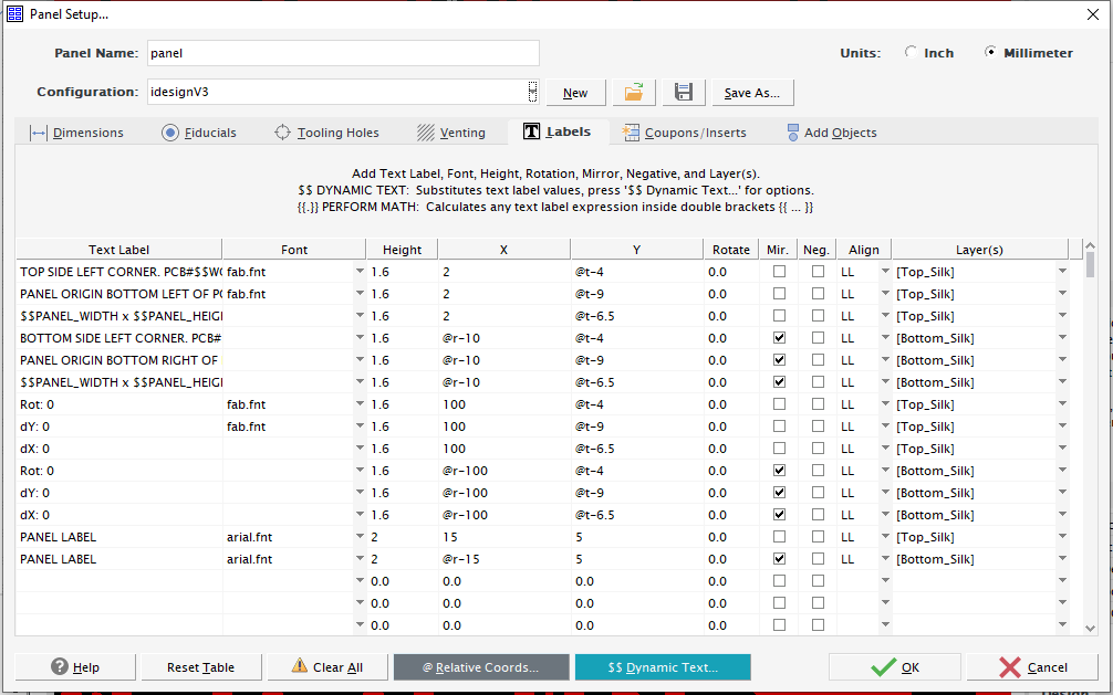
Add Text Label to the active Panel.
- Text Label: Enter the text you require on the panel. All dynamic Text variables are fully supported, https://support.numericalinnovations.com/support/discussions/topics/14000018603
- Font: Choose the font you wish for the Text label. FAB 3000 supports almost any TrueType or AutoCAD SHX font, so if you don't see a specific font you require it can be compiled into a FAB 3000 font file (*.fnt). https://support.numericalinnovations.com/support/discussions/topics/14000003029
- Barcodes are supported. FAB 3000 comes with several Bar Code fonts already included. You can compile any existing TrueType font into a FAB 3000 font file (*.fnt) that may be used within your panel, https://support.numericalinnovations.com/support/discussions/topics/14000003119
- Height: Enter the Text height you require.
- Insert Point X, Y: Assign the Lower-left insert point for the text.
- Mirror: If checked Text will be mirrored Horizontally (about the Y axis).
- Negative: If checked text will be clear. Make sure text is over an existing metal area or else it will appear invisible.
- Align: Align text label about the Insert Point (X,Y). There are 9 alignment values available, and the default is LL (Lower Left).
- LL Lower Left.
- CL Center Left .
- UL Upper Left .
- LC Lower Center.
- CC Center Center. (exact middle of text)
- UC Upper Center.
- LR Lower Right.
- CR Lower Right.
- UR Lower Right.
- Layer(s): Select the layers for the Text to appear.
IMPORTANT: Relative Panel Coordinates are Recommended:
You may use Relative Panel Coordinates requires the at-sign @ (See below link for examples)
| Coupons / Inserts |
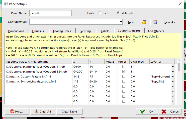
Insert Coupons and other external resources into the Panel.
- Resource (*.job, *.fm6, Job name): Resources include: Job files (*.job), Matrix Files (*.fm6), and existing Job/Panels (already loaded and available in the FAB 3000 Workspace).
- Note: Job files (*.job) and Matrix files (*.fm6) must include the absolute path (no relative paths).
- Insert Point X, Y: Assign the insert point for the external resource.
- Rotate (degrees): Assign the rotation for the inserted external resource. Default is 0.0.
- Mirror: If checked the external resource will be mirrored Horizontally (about the Y axis).
- Clearance: Add a clearance around the inserted external resource. Set 0 for no clearance.
- Layer(s): Optional - only used only by Matrix files (*.fm6) using "active" for the layer. https://support.numericalinnovations.com/support/discussions/topics/14000012956
IMPORTANT: Relative Panel Coordinates are Recommended:
You may use Relative Panel Coordinates requires the at-sign @ (See below link for examples)
Add Objects |
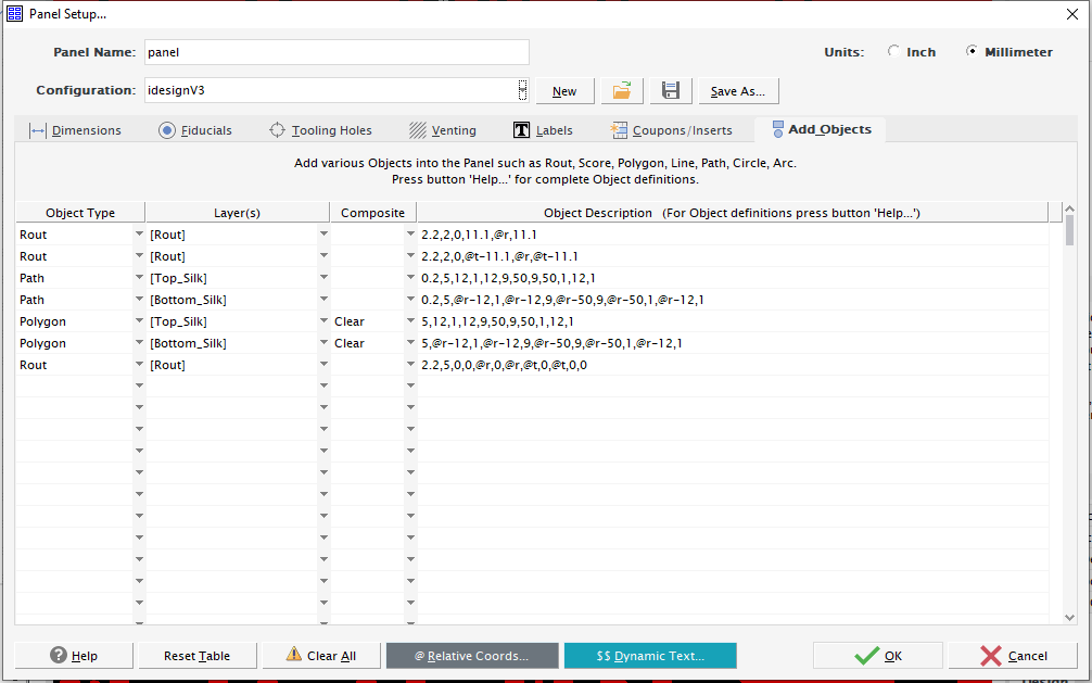
Add various Objects into the Panel such as: Rout, Score, Polygon, Line, Path, Circle, Arc, Image
Note: All Object Descriptions are comma separated. Relative Panel Coordinates are recommended and requires the at-sign @
Composite:
Determine whether all following objects will be added as either: Dark, Clear, or Composite Level. For more information about composites, please view Help Center: About Composites
Note: If blank, the default is Dark.
Examples:
COMPOSITE=DARK
COMPOSITE=CLEAR
COMPOSITE=51
Note: Using a "Composite Level" Number will allow you to directly assign a composite level number. When choosing Dark or Clear, FAB 3000 automatically determines what composite level to use.
Rout Description:
WIDTH,POINT_COUNT,[X],[Y],[...]
- WIDTH is the rout path tool width.
- POINT_COUNT is the number of points for the nc path.
- X,Y,... are the X,Y point array.
Example: 2.2,2,0,10,@Right-0,10
Score Description:
X1,Y1,X2,Y2
- X1,Y1 is the start point.
- X2,Y2 is the end point.
Note: Score lines only contain two points and are typically orthogonal.
Example: @ml@mb,@mr,@mb
Polygon Description:
POINT_COUNT,[X],[Y],[...]
- POINT_COUNT is the number of points for the path.
- X,Y,... are the X,Y point array.
Example: 5,@r-12,1,@r-12,9,@r-50,9,@r-50,1,@r-12,1
Line Description:
POINT_COUNT,[X],[Y],[...]
- POINT_COUNT is the number of points for the path.
- X,Y,... are the X,Y point array.
Example: 7,-9,-9,-9,-8,-8.25,-8,-8.25,-6,-2,-6,-2,-9,-9,-9
Path Description:
WIDTH,POINT_COUNT,[X],[Y],[...]
- WIDTH is the path width.
- POINT_COUNT is the number of points for the path.
- X,Y,... are the X,Y point array.
Example: 0.2,5,@r-12,1,@r-12,9,@r-50,9,@r-50,1,@r-12,1
Circle Description:
X,Y,OD,ID
- X, Y are the Circle Center coordinate.
- OD is the Circle Outer diameter
- ID is the Circle inside diameter. This is optional, and the default is 0.
Example: 0.25,0.25,0.1,0.05
Arc Description:
SX, SY, EX,EY,CX,CY,COUNTER-CLOCKWISE DIRECTION,LINEWIDTH
- SX, SY are the Arc start coordinate.
- EX, EY are the Arc end coordinate.
- CX, CY are the Arc center coordinate.
- COUNTER-CLOCKWISE DIRECTION is Y for Counter-Clockwise, or N for Clockwise.
- LINEWIDTH is the line width for the Arc
Example: 1,0,0,1,0,0,Y,0.1
Requires FAB 8.6+
Image Description:
X,Y,WIDTH,HEIGHT,<IMAGE_FILE_LOCATION>
- X, Y are the Image origin coordinate (i.e lower-left placement of image).
- WIDTH is the image size scaled to width. If 0, then HEIGHT is used for for image scale.
- HEIGHT is the image size scaled to height. If 0, then WIDTH is used for for image scale.
- <IMAGE_FILE_LOCATION> is the file path location where the image exists. Use absolute paths and must be in quotes.
Note: Importing images is perfect for including company logos, QR codes, Bar Codes, and more. Image formats supported are: png, bmp, jpeg, gif, and tif. Images should have less than 5k pixels (per side).
Example: @r-0.4,@cy-0.15,0.3,0.3,"C:\Panel_Images\QR-code\website_qr_.png"
Other Helpful Resources |
- Panel Setup: Using Relative Panel Coordinates
- Create your own Panel template (from previous set of Panelized Gerbers).
Was this article helpful?
That’s Great!
Thank you for your feedback
Sorry! We couldn't be helpful
Thank you for your feedback
Feedback sent
We appreciate your effort and will try to fix the article